GPX 250 Twin Dashboard Pinout & Removal: Instrument Cluster Signals
The GPX 250 Twin instrument cluster (dashboard) is the main signal hub containing all necessary wiring for keyless start systems, self-cancelling turn signals and trip computers.
Why the GPX 250 Twin Dashboard Suits Keyless and Self-Cancelling Systems
- All important signals (speed, tachometer, turn indicators) are available on the 20-pin Molex connector of the instrument cluster.
- No CAN-bus — the dashboard uses straightforward analog signals.
- True Keyless from SmartMoto.Asia is designed with the GPX 250 Twin dashboard in mind, including TVS diode protection against voltage spikes up to 90 V (stock cluster has no such protection).
Most aftermarket systems connect directly to the dashboard connector. True Keyless offers full plug-and-play compatibility with the stock GPX 250 Twin instrument cluster.
How to Remove the GPX 250 Twin Instrument Cluster – Step by Step
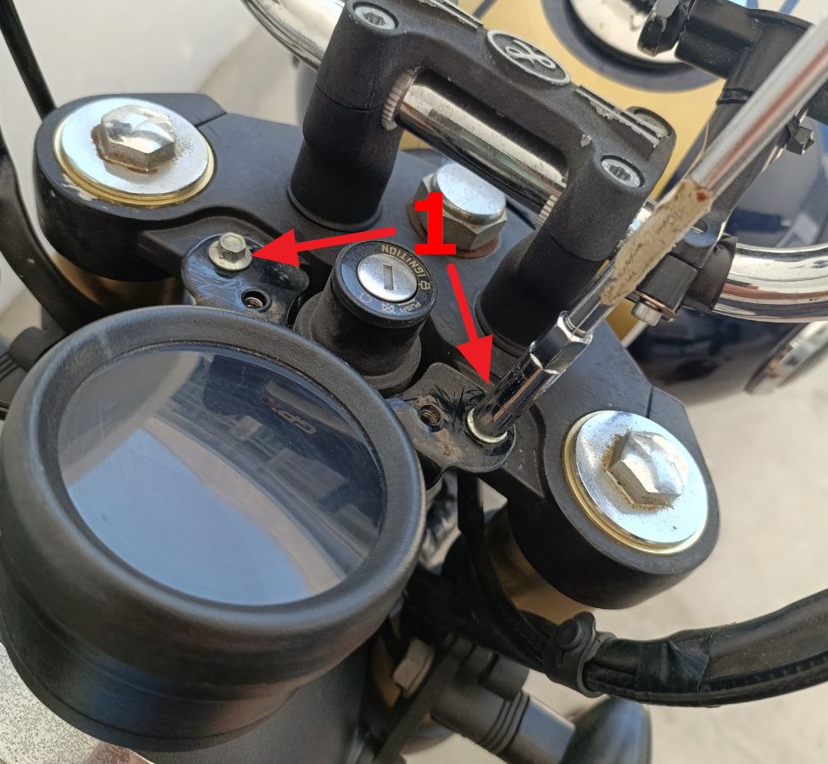
- Use a Phillips screwdriver to remove the two screws holding the plastic trim and carefully take it off.
- With an 8 mm wrench, remove the two bolts securing the instrument cluster bracket.
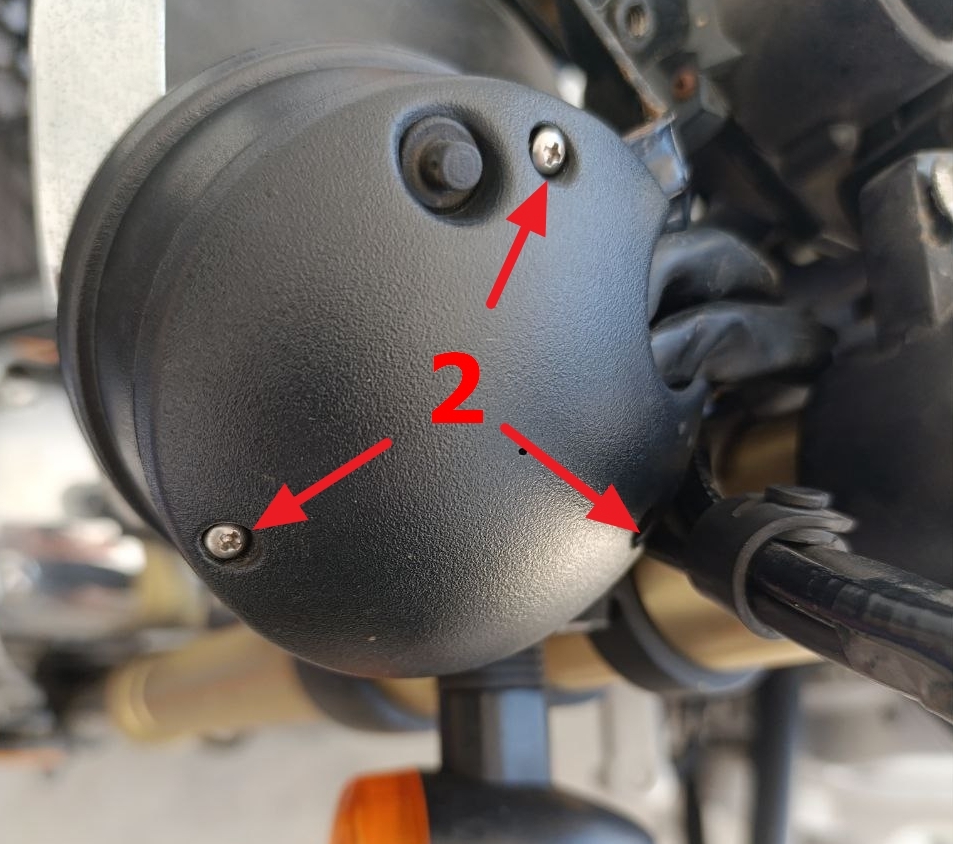
- Flip the cluster over and use a small Phillips screwdriver to remove the three screws on the bottom cover → lift off the cover.
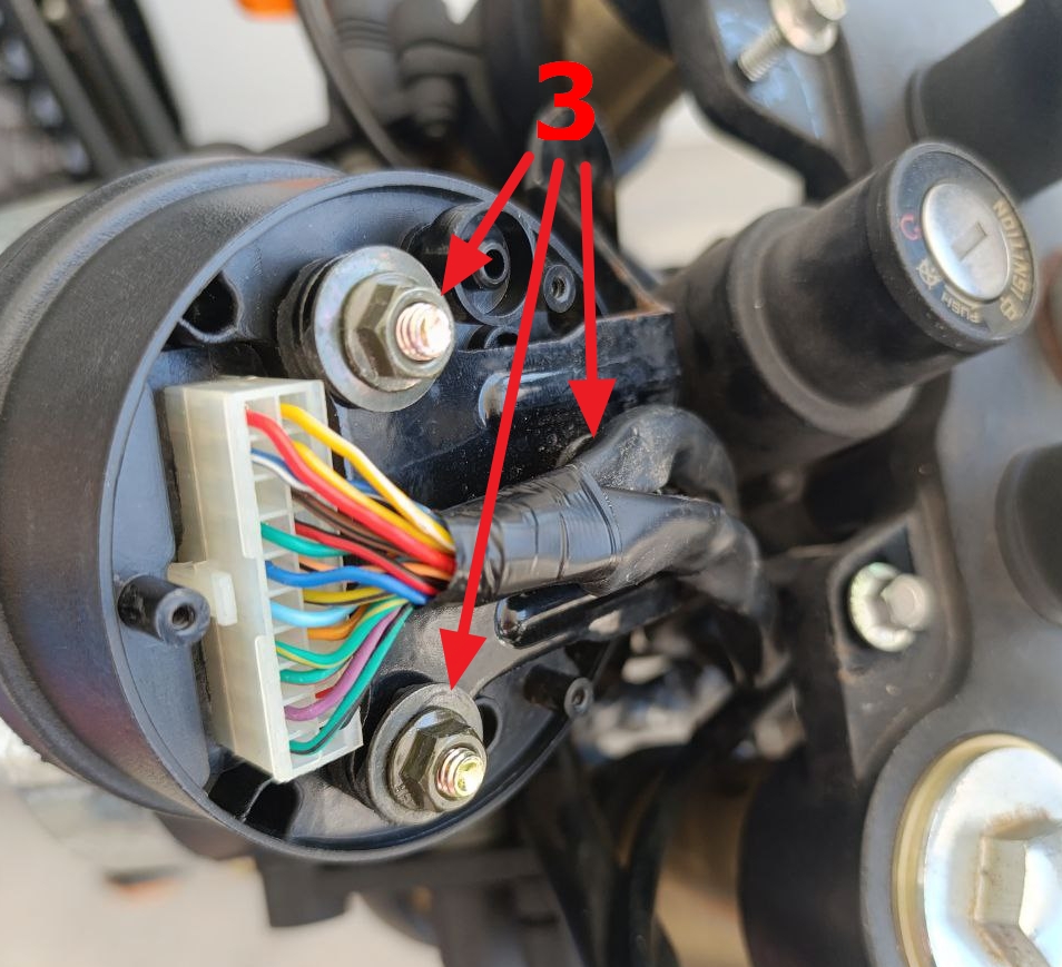
- You’ll now see the main 20-pin Molex Mini-Fit Jr. connector (4.2 mm pitch) — this is where all dashboard signals are located.
- Disconnect the connector and remove the cluster.
- If required, use an 8 mm wrench to remove the three nuts holding the bracket.
Reinstallation is the reverse process.
GPX 250 Twin Instrument Cluster 20-Pin Connector Pinout
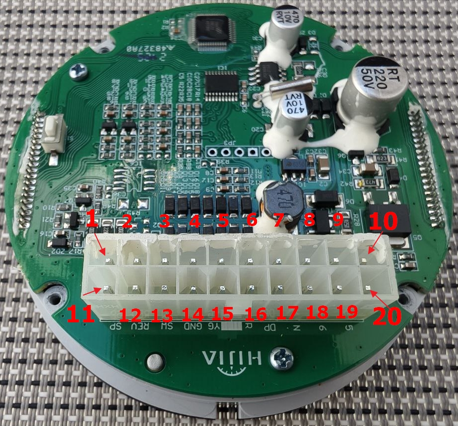
| Pin | Function | Technical Details | Useful for |
|---|---|---|---|
| 1 | Fuel sensor | 5V via 220 Ω | Trip computer (future) |
| 2 | Speed Sensor Power | +5V (via 220 Ω) | Trip computer |
| 3 | Gear 1 | Shorts to GND when engaged | Gear indication |
| 4 | Gear 2 | Shorts to GND when engaged | Gear indication |
| 5 | Gear 3 | Shorts to GND when engaged | Gear indication |
| 6 | Gear 4 | Shorts to GND when engaged | Gear indication |
| 7 | Left Turn Lamp | +12V activation | Self-cancelling turn signal (left) |
| 8 | ABS Lamp | DNP (not used) | — |
| 9 | Battery + | Constant +12V (clock/memory) | Power for keyless systems |
| 10 | Ignition + | +12V after ignition switch | Keyless start |
| 11 | Speed Signal | ~3.5V amplitude | Trip computer + turn signal logic |
| 12 | Tachometer | 12V amplitude, ~40 ms at 1500 rpm | Trip computer |
| 13 | SW | DNP | — |
| 14 | Ground | Battery negative | Any system |
| 15 | High Beam Lamp | +12V activation | — |
| 16 | Right Turn Lamp | +12V activation | Self-cancelling turn signal (right) |
| 17 | Check Engine | Active low (short to GND triggers) | Diagnostics |
| 18 | Neutral | Shorts to GND when engaged | Gear indication |
| 19 | Gear 6 | Shorts to GND when engaged | Gear indication |
| 20 | Gear 5 | Shorts to GND when engaged | Gear indication |
Main dashboard signals for common systems:
- Trip computer → Pin 11 (speed) + Pin 12 (tach)
- Self-cancelling turn signals → Pin 7 (left) + Pin 16 (right) + Pin 11 (speed)
- Keyless start → Pin 10 (+12V ignition) + Pin 14 (ground)
Bench Testing the GPX 250 Twin Instrument Cluster
For debugging or compatibility checks directly from the dashboard:
- Apply +12V to Pin 9 (battery) and Pin 10 (ignition).
- Connect ground to Pin 14.
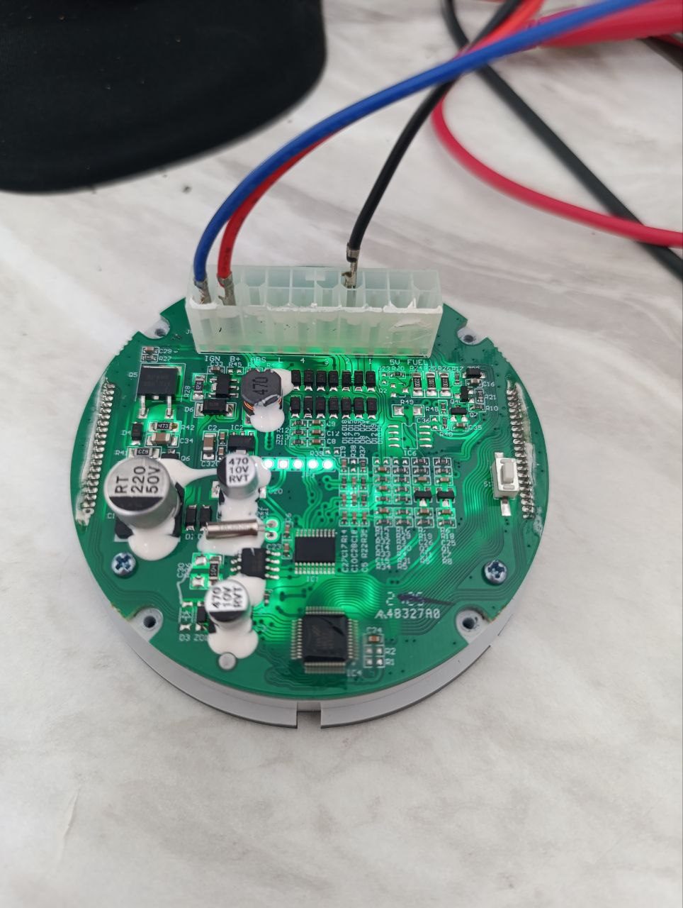
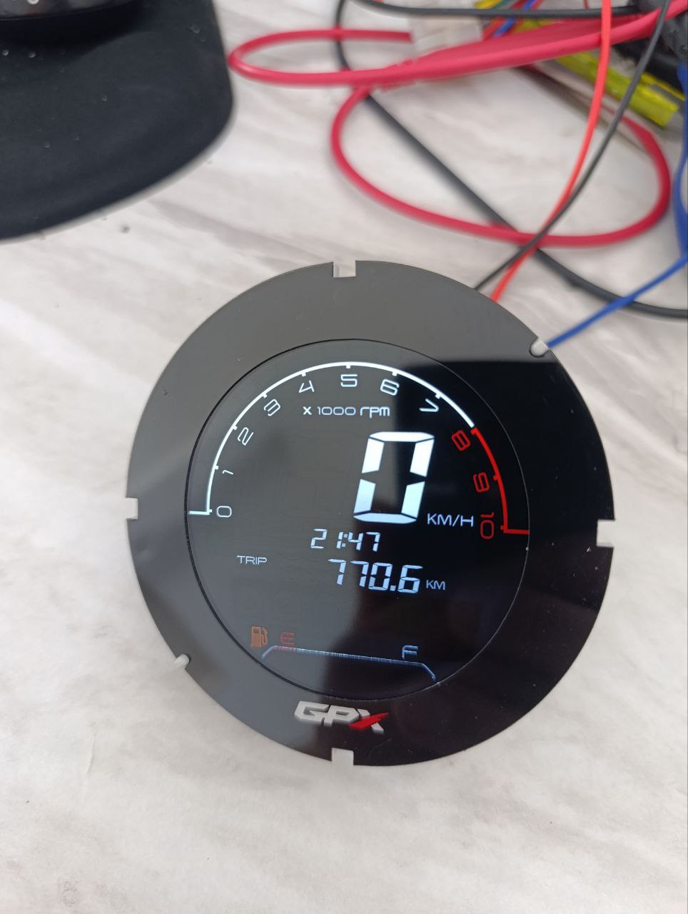
The instrument cluster will power up, allowing you to simulate signals and verify compatibility.
Disassembling the GPX 250 Twin Instrument Cluster
Disassembly should begin with the most challenging step — removing the top cover (glass bezel). Take a close look: you will see a thin gap between two parts of the housing — the glass frame and the main body. The glass frame needs to be rotated counterclockwise slightly and then lifted upward. This is not easy because, in addition to the grooves, there is also sealant holding it in place. Be firm but careful to avoid damage.
Once the top cover is removed, unscrew the 4 screws located in the recesses on the bottom side of the housing. Then gently push the board with the display upward from below. Do not try to pry the display from the top — you will damage it. Push from the bottom only.
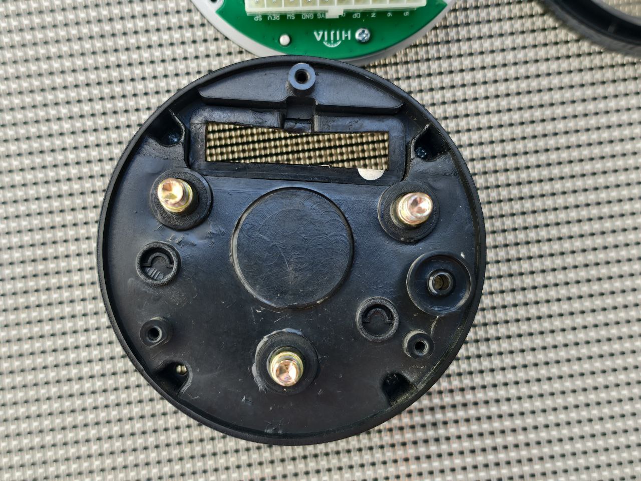
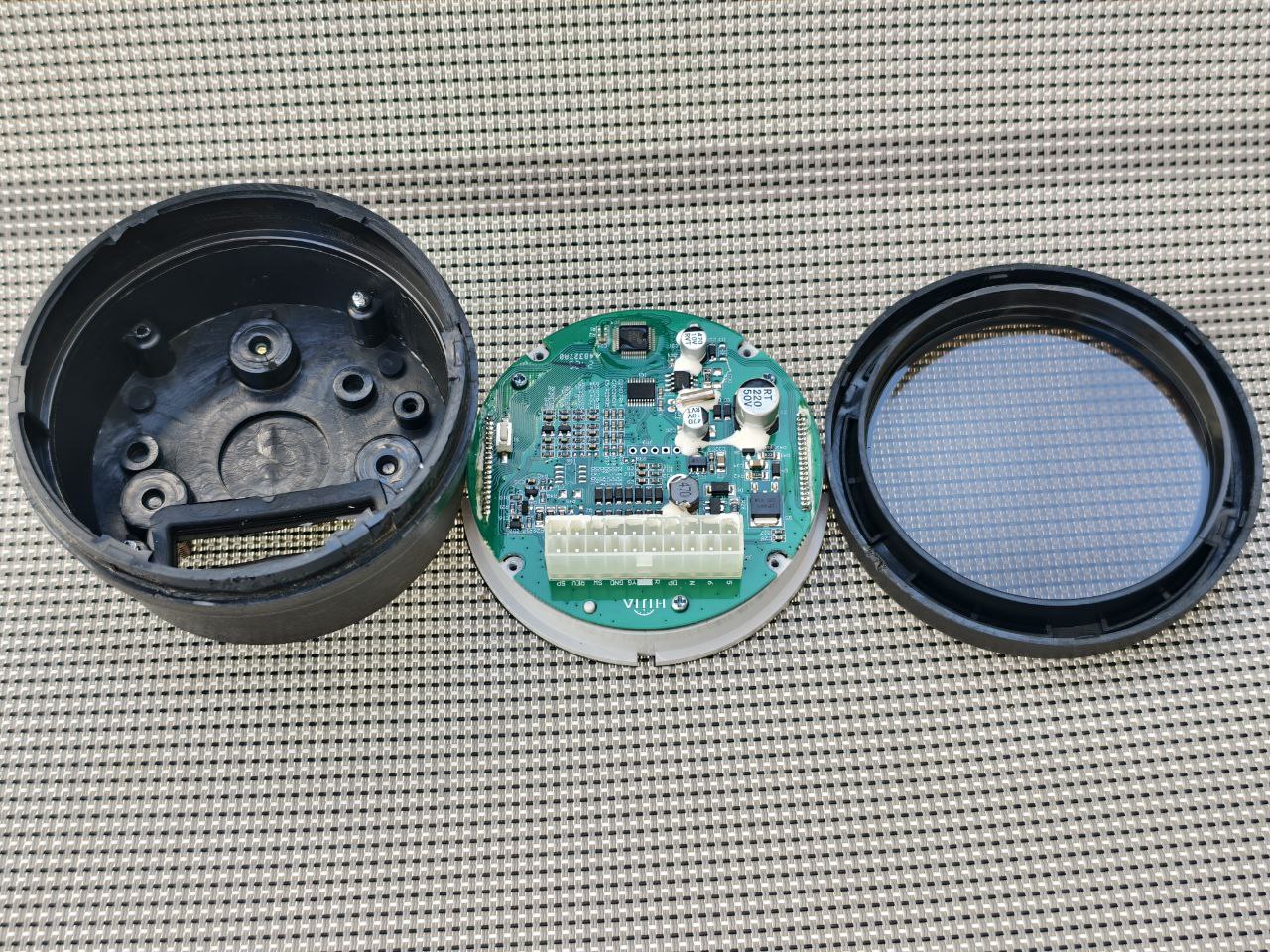
Congratulations — the instrument cluster is now disassembled, and the board with the display is in your hands.
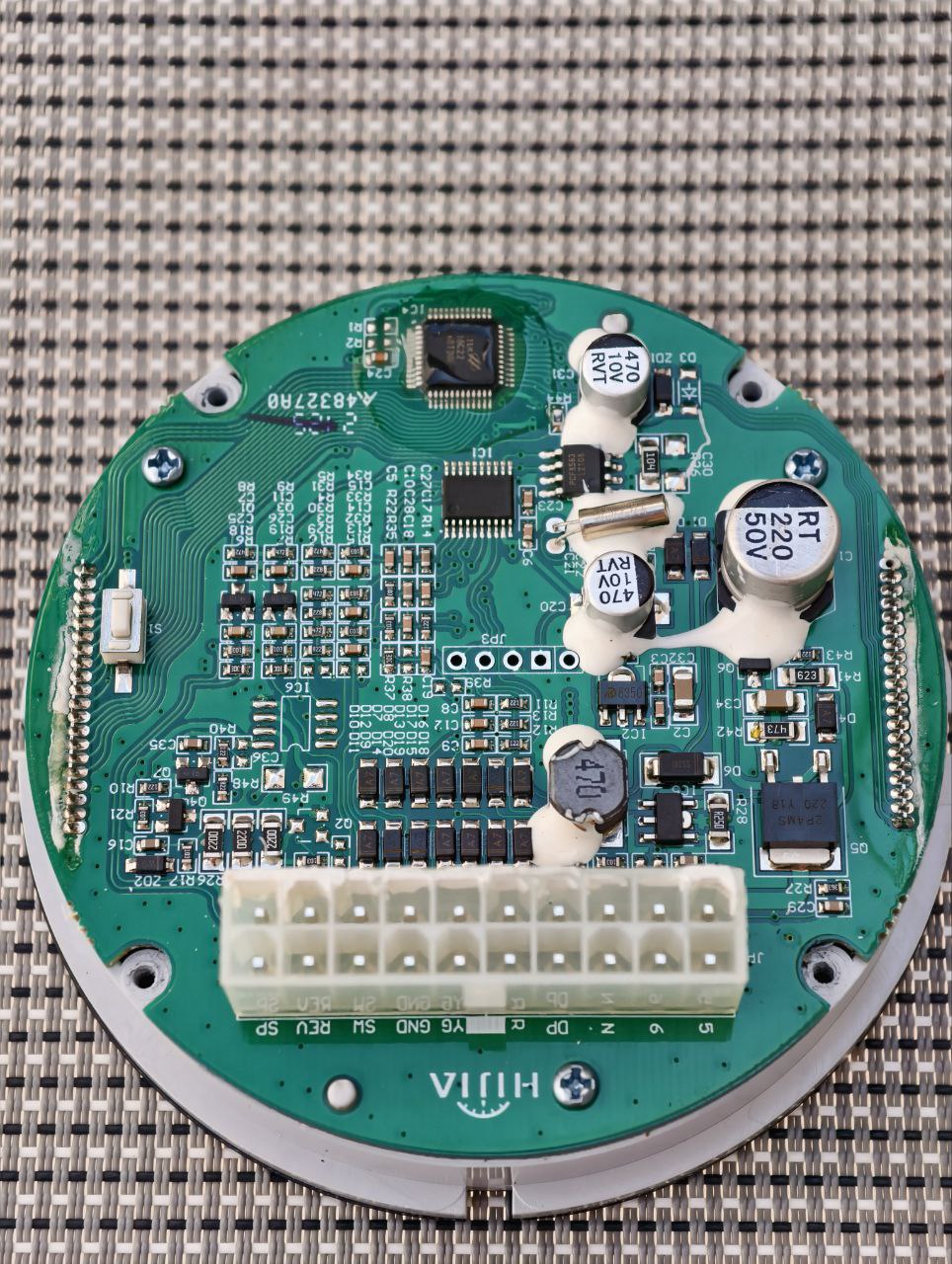
Inside the GPX 250 Twin Instrument Cluster (Reverse Engineering Overview)
Looking at the board, the following main components are immediately visible:
Click the image to open in full size
Click the image to open in full size
- MCU — marking is worn off, but it strongly resembles a CH32V003F4P6
- RTC (real-time clock) — no battery on the board, so time is maintained only by capacitor charge while powered
- LCD display controller
- DC-DC current stabilizer for LED backlight power
- LDO regulator for powering the processor
- Isolation and level-matching circuits for digital and analog inputs
What I did not find — and this is quite surprising — is any meaningful power supply protection circuitry. This is unusual because motorcycle electrical systems can produce prolonged high-voltage spikes, up to 90 V. In contrast, the True Keyless system from SmartMoto.Asia for the GPX 250 includes powerful TVS diodes on all power lines for reliable protection.
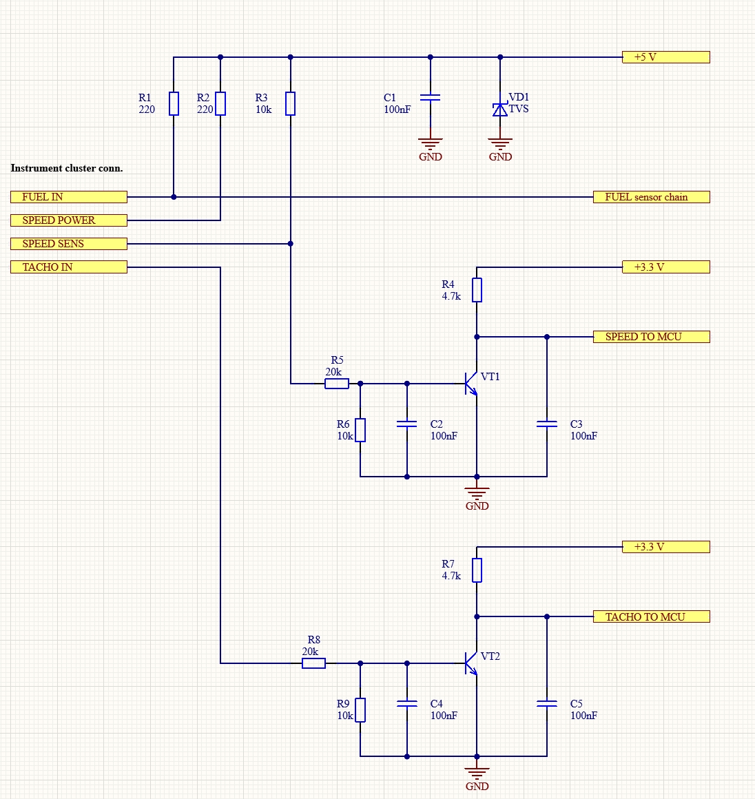
Click the image to open in full size
I performed a small reverse-engineering effort, mainly focusing on the input circuitry for the speed sensor and tachometer signals. The schematic is attached below. For those familiar with electronics, no further explanation is needed. If you have questions — feel free to ask via the contact form.
Why True Keyless Works Well with the GPX 250 Twin Dashboard
- Designed specifically for the GPX 250 Twin instrument cluster
- Plug-and-play compatibility — no modifications to dashboard wiring
- Robust TVS diode protection against electrical spikes
- Compatible with stock dashboard signals
- 100% compatibility with GPX 250 Twin wiring
Frequently Asked Questions about the GPX 250 Twin Dashboard
How do I connect a trip computer to the GPX 250 dashboard?
Use Pin 11 for the speed signal and Pin 12 for the tachometer signal. True Keyless integrates these dashboard signals seamlessly.
Do self-cancelling turn signal systems require changes to the instrument cluster?
Most third-party systems need access to Pins 7, 16, and 11. True Keyless uses dashboard signals without any modifications.
Is the stock GPX 250 dashboard protected from voltage spikes?
No — the factory instrument cluster lacks spike protection. True Keyless includes powerful TVS diodes for better reliability.
Can I bench-test the GPX 250 Twin instrument cluster?
Yes — supply +12V to Pins 9 and 10, and ground to Pin 14. The display will activate for signal testing.
Questions about the GPX 250 Twin dashboard, pinout, removal or compatible systems? Contact us at www.smartmoto.asia