Installation Guide
Step-by-step installation instructions for True Keyless system
True Keyless GPX - easy installation on GPX motorcycles
GPX 250 TwinGPX 250 Twin 2GPX 250 Twin 3GPX 250 BrightonGPX Demon G200RGentleman 200
For GPX motorcycles we are using a dedicated wiring harness that connects directly to the stock connectors. Installation is simple and takes 1-2 hours.
Installation Steps
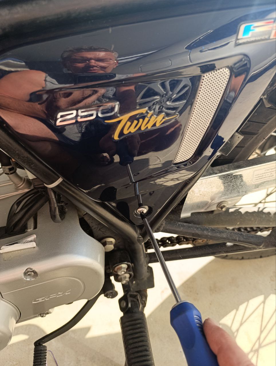
- 1Unscrew the screw with a Phillips screwdriver, remove the battery cover and disconnect the negative terminal
- 2Remove the seat (2 x 10mm bolts) and unscrew the fuel tank mounting bolts (2 x 8mm bolts)
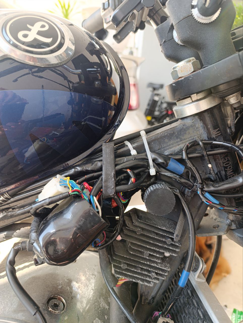
- 3First pull the tank slightly backward, then carefully lift and secure the front part of the fuel tank without damaging the fuel lines
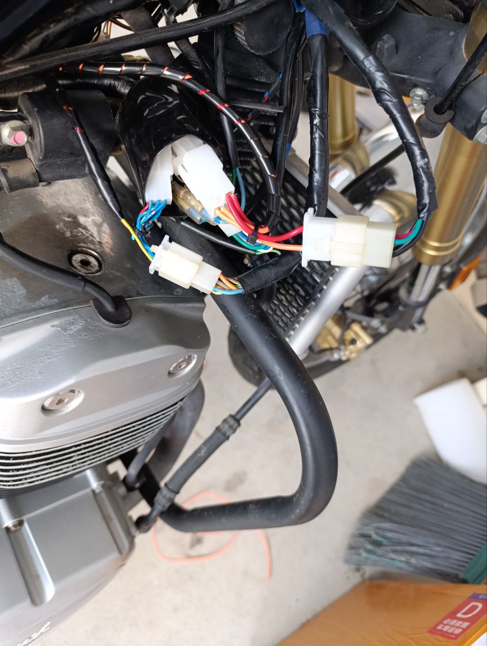
- 4Connect True Keyless connectors to the standard wiring on both halves - 9-pin green connectors of the left switch to the black connectors of the system
- 5Left side - 3-pin speed sensor connectors to the 3-pin connectors of the system
- 6Right side - 9-pin white connectors of the right switch to the white 9-pin connectors of the system
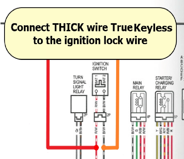
- 7Right side - 4-pin ignition lock connectors to the 4-pin connectors of the system
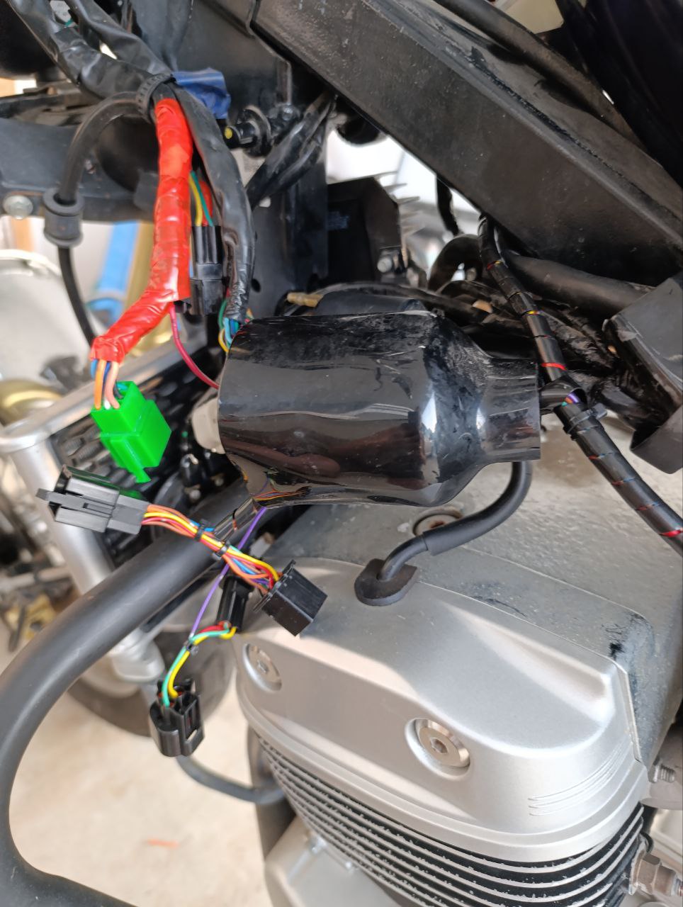
- 8Place the connectors in rubber covers and press them tightly against the frame so they don't interfere with tank reinstallation
- 9Open the diagnostic connector cover on the right, unscrew the connector mounting screws and rotate it at an angle. Insert the mating connector from the system. Secure with a plastic tie. Connect the cable from the diagnostic connector to the main system harness.
- 10Secure the electronic unit to the frame in the battery compartment with a plastic tie, moving aside the standard connectors
- 11Reinstall the tank and battery cover
- 12Start system operation: enter the PIN code and pair your phone
- 13Test the ignition, starter, and turn signals operation


Installation with Universal Wiring Harness
Royal EnfieldSuzukiKawasakiHondaTriumphDucati
Universal harness allows installation on any motorcycle. Requires basic wiring knowledge and identification of key circuits.
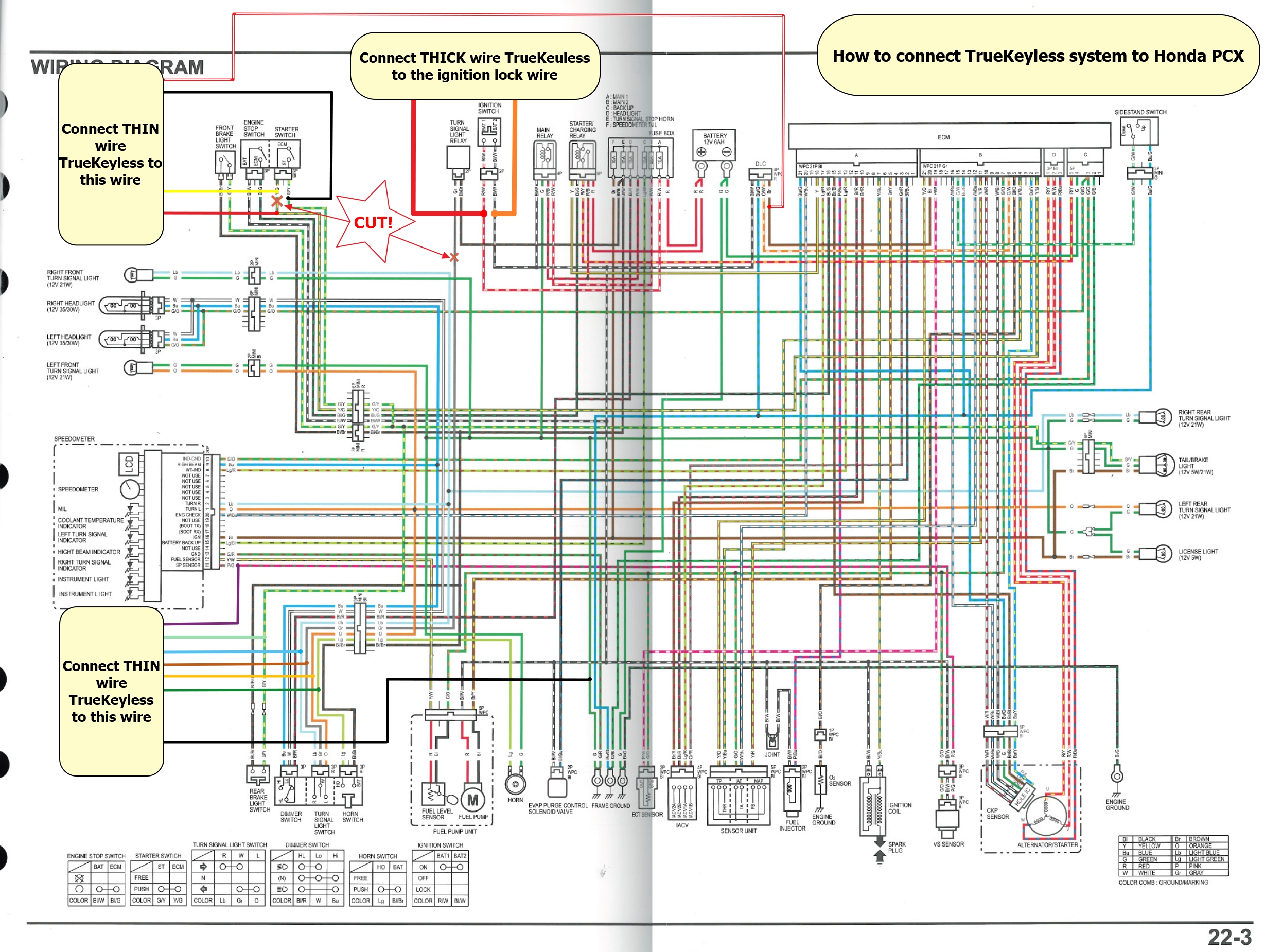
Wiring Diagram
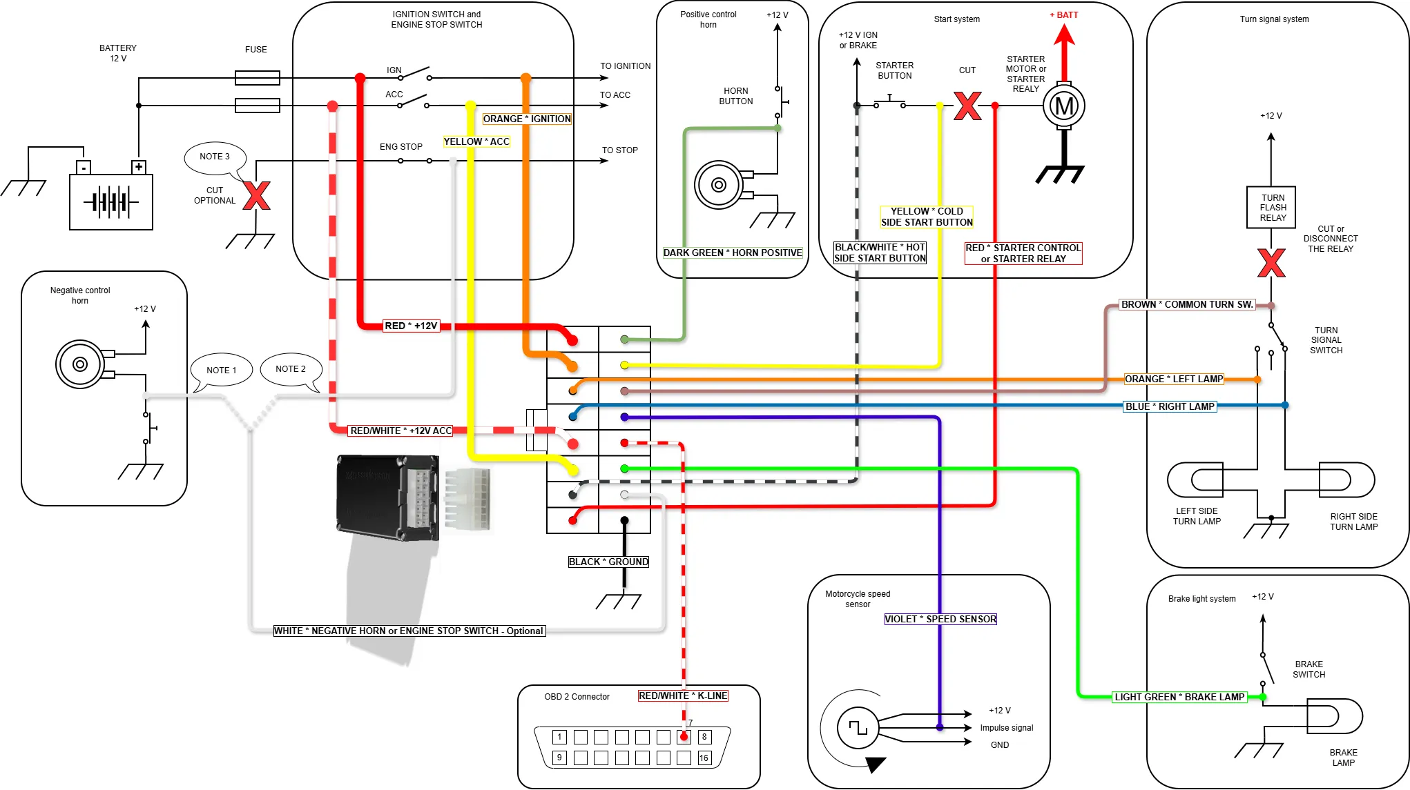
Click on the image to open in full size
Wiring Connection Table
| No. | Color (Type) | Purpose | Connection | Comments |
|---|---|---|---|---|
| 1 | Red (thick) | System power input | To constant +12V from battery, through 15A fuse | Overvoltage protection. Main module power. Powers ignition output. Powers turn signals. |
| 2 | Orange (thick) | Ignition output (IGN) | To standard IGN circuit of ignition switch | Max current: 10A. Short circuit protection. Supplies +12V when ignition is turned on by system. |
| 3 | Orange (thin) | LEFT turn signal output | To wire going to left turn signal lamps | Max current: 10A. Short circuit protection. Controls flashing. |
| 4 | Blue (thin) | RIGHT turn signal output | To wire going to right turn signal lamps | Max current: 10A. Short circuit protection. Controls flashing. |
| 5 | Red-white (thick) | ACC output power input | To constant +12V only if there is standard ACC circuit | Connect to constant +12V wire after ACC fuse. If no ACC circuit exists — insulate. |
| 6 | Yellow (thick) | ACC output | To standard ACC circuit consumers – wire after ignition switch | Max current: 10A. Short circuit protection. Supplies +12V when activated. |
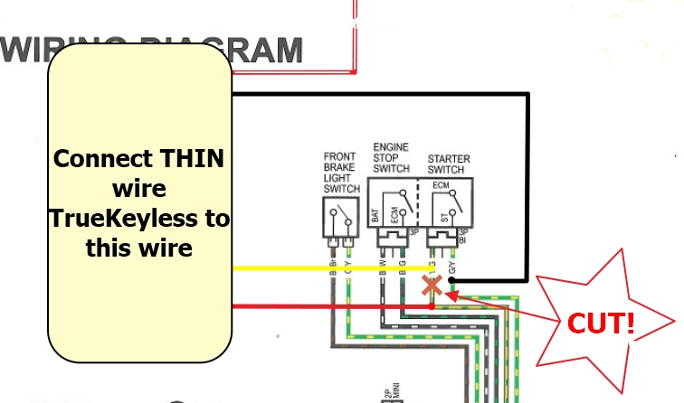
| 7 | Black-white (thin) | Starter button signal input | To starter button wire where +12V appears when ignition is on | Voltage for powering starter circuit through True Keyless block. Critical for operation. |
| 8 | Red (thin) | Starter output | To starter relay control terminal or solenoid | Max current: 10A. Short circuit protection. Takes voltage from black-white wire and activates starter on command. |
| 9 | Green (thin) | Horn output (+) | To horn wire where +12V appears when horn is pressed | Controls horn via 'positive'. If voltage disappears when pressing horn (becomes about 0 volts) then use white wire (15) for horn connection. See diagram. |
| 10 | Yellow (thin) | Starter button control input | Connect to starter button wire where +12V appears only when starter button is pressed | Required. Diagnostics: in standby +6V, when pressed >10V. Or less than 3 volts. Detects moment of starter button press. |
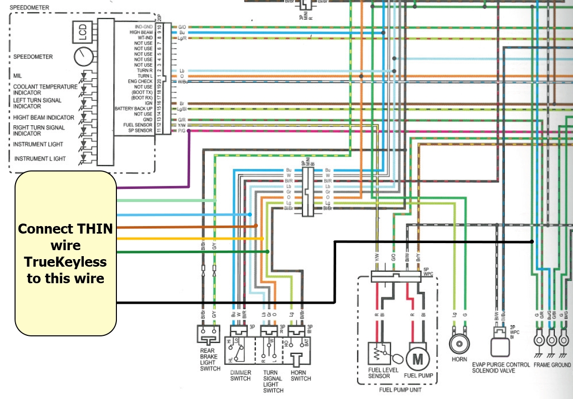
| 11 | Brown (thin) | Turn signal switch input | To central contact of switch after breaking circuit with old relay | Break standard circuit! Diagnostics: in neutral +6V, when activated >10V or 0V. |
| 12 | Purple (thin) | Speed sensor input | To signal wire of speed sensor (pulses 5V/12V), 1-10 pulses per 1 wheel revolution | Without it: no smart turn signals, phone notifications, trip computer. |
| 13 | Red-white (thin) | Diagnostic bus input | To signal line of OBD diagnostic connector (protocol depends on model) | Without it: no restart protection, overheating indication, Check Engine diagnostics. |
| 14 | Green (thin) | Brake signal input | To brake light wire where +12V appears when braking | Used for start and engine kill logic. Must be connected. |
| 15 | White (thin) | Universal negative output (mode set in settings) | Option A: to horn wire controlled by 'ground'. Option B: to ENGINE STOP button | Mode selected in application. Default — not used, insulate. Protection against short to +12. |
| 16 | Black (thin) | Ground (GND) | Directly to battery '–' terminal or to standard wire always and reliably connected to ground | Mandatory connection. Unreliable connection is the cause of all failures. |
Installation Steps
- 1Study the wiring diagram for your motorcycle model. Look at the your service manual page.
- 2Remove necessary parts to access wiring (tank, plastics)
- 3Identify wires: +12V, ground, ignition, turn signals, horn, speed sensor, K-line of diagnostic connector, brake light wire, starter button
- 4Connect universal harness according to diagram
- 5Secure electronic unit in protected location
- 6Reassemble motorcycle and test all system functions
- 7If necessary, in settings set correct horn polarity and negative engine kill wire behavior - depends on motorcycle model